Polygon Session
We begin our introduction to sessions with the simplest one - the polygon session. The polygon session is backed by Boost.polygon which is only available in 2D. It is named “polygon session” because the geometry is limited to combinations of polygons. This is currently the only session that allows the user to create a model in ModelBuilder instead of importing it (File - New polygon model). Next we introduce some features of this session.
Note
The features of introduced do not have to be exclusive. Some of them are shared by multiple sessions.
Model Operations
A model will be automatically created when the polygon session starts. Right-click on the entity tree to create, close and save a model. Multiple models can be grouped by clicking Model - Create Group. Right-click on the model in the entity tree, select Model - Export edges to VTK, a window similar to this figure will pop out:
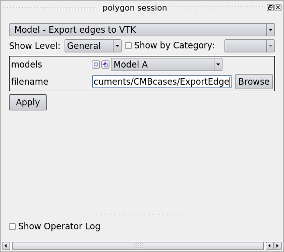
Select the target model, fill out the filename and hit apply, the edges will be exported to VTK.
Auxiliary geometry can be added to a model if necessary. Auxiliary geometry is a file that contains additional information which can be visualized on the model (for instance temperature data), or simply used as a background. A variety of data formats can be used as auxiliary geometry including .tif, .tiff, .dem, .vti, .vtp, .vtu, .vtm, .obj, .pts, .xyz. “Add an image” is a similar option to load auxiliary geometry except that it only accepts .tif, .tiff, .dem and .vti files. We will talk more about adding auxiliary geometry in The Discrete Session
Entities can be deleted by clicking Model Entities - Delete. Sometimes it is convenient to color the model entities so that they look more distinct to each other. This can be done with Model Entities - Assign Colors.
Vertex Operations
Vertices can be added using exact coordinates through “Vertex - Create” and removed through “Vertex - Demote”.
Edge Operations
Edges can be created interactively:
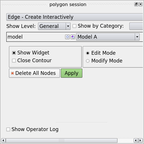
Click on Edge - Create Interactively, select the model you want to create edges for in the polygon session window:
Next you can left-click in the viewport to create a vertex. A poly-linear line will be generated following the vertices created. You can click on “Close Contour” to connect the first and last vertices. Hit “Apply” to commit the changes.
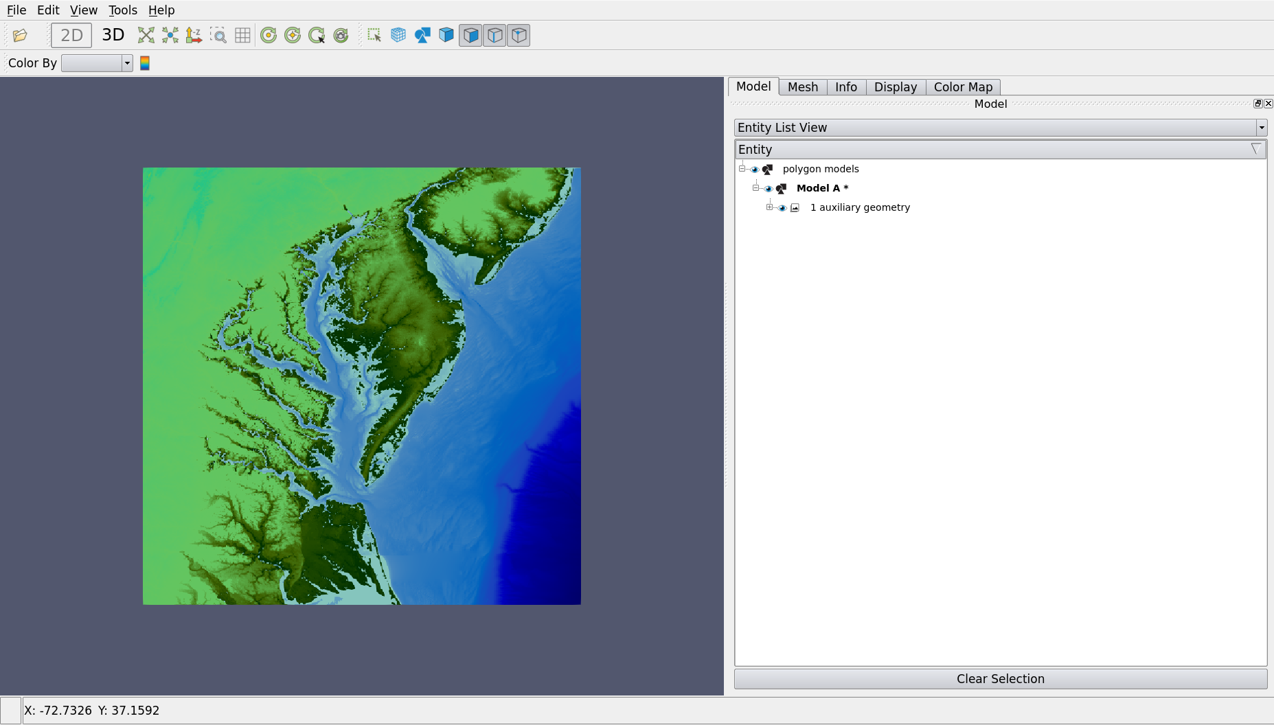
If you want to create an edge with exact coordinates, use Edge - Create from Points. A tabular will be available to enter point coordinates. If vertices are already created, you can form edges through them by using Edge - Create from Vertices. If we have auxiliary geometry imported, we can even create edge from the contours. To show this, we first load an auxiliary geometry through Model - Add Auxiliary Geometry. See The Discrete Session for more instructions. Here is a figure of an auxiliary geometry:
Now, right-click on the model and select Edge - Create From Contours, in the following window specify the auxiliary geometry, and click “Launch Contour Preview”. A contour generator will appear, which lets you to specify the opacity, contour value and minimum line length.
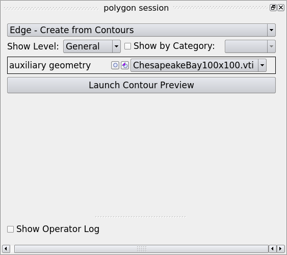
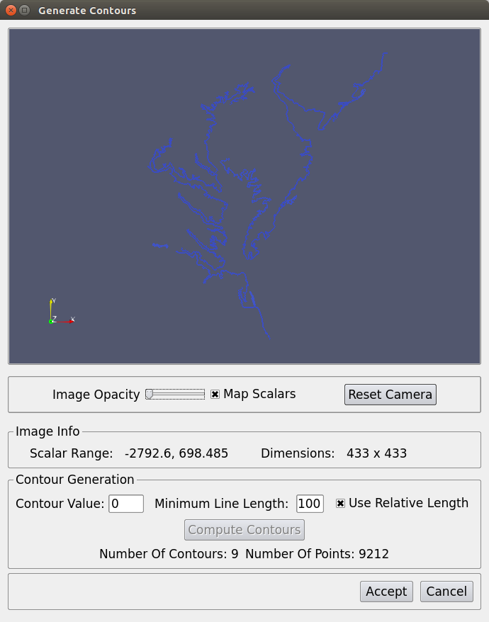
It is a good idea to turn down the image opacity in the preview, so that you can see the contour more clearly. The “Contour Value” is the data value that you want to extract at; the generated line segments that is shorter than the “Minimum Line Length” will be trimmed off. Once the contours are computed, you can find the number of connected contours and number of points on those contours in the same window. Click “Accept” if you are satisfied with the result. You will see edges and vertices created in your polygon model.
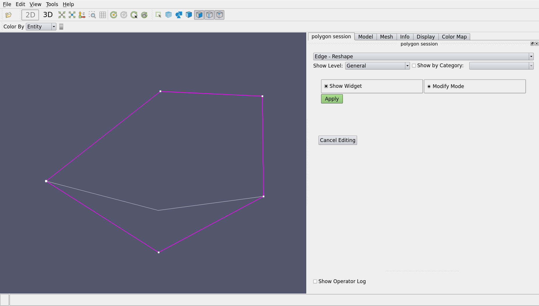
An edge can be reshaped using “Edge - Reshape”. To do so, right-click on the model tree and select “Edge - Reshape”. Then click on “select edge to edit” and box-select an edge, then drag the vertices on the screen or type in the coordinates in “Advanced” mode.
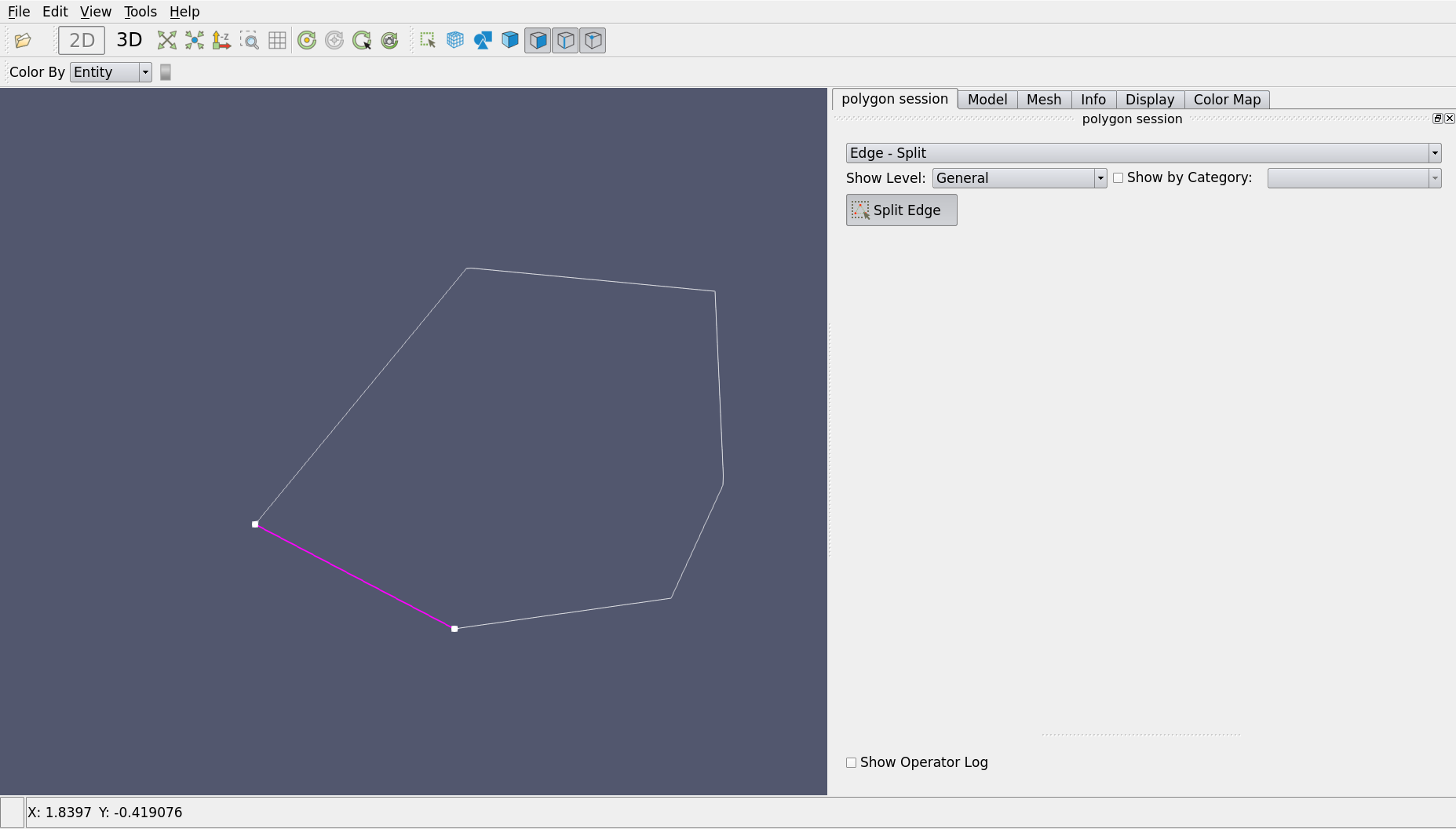
Similarly to reshape, an edge can be split interactively with a vertex through “Edge - Split”. As shown in the figure below, a closed edge is split into two:
Note
“Edge - Reshape” and “Edge - Split” can only be performed on edges with more than 2 vertices.
Face Operations
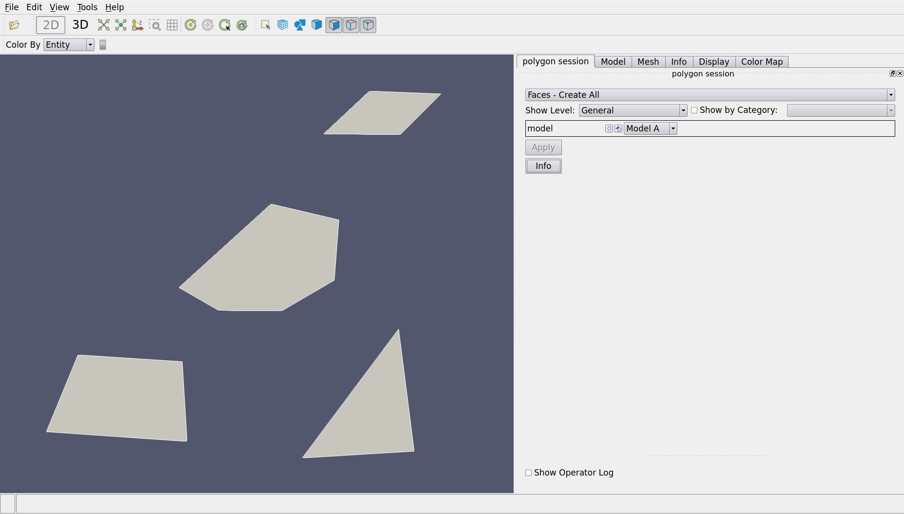
Faces are created from edges. “Create from Edges” allow the user to create a face from the selected edges while “Create All” will create multiple from all the closed edges in a model.
Mesh Operations
If a mesh is created or loaded, it will also be shown in the model tree. Mesh can be deleted, saved or exported. However, currently ModelBuilder is unable to generate mesh, you must have an external mesher to do that.
See also
The Mesh Tab for using external mesher with ModelBuilder.
Another interesting operation available for mesh is interpolation, which creates a field variable either on cell fields or point fields. Right-click on Mesh - interpolate:
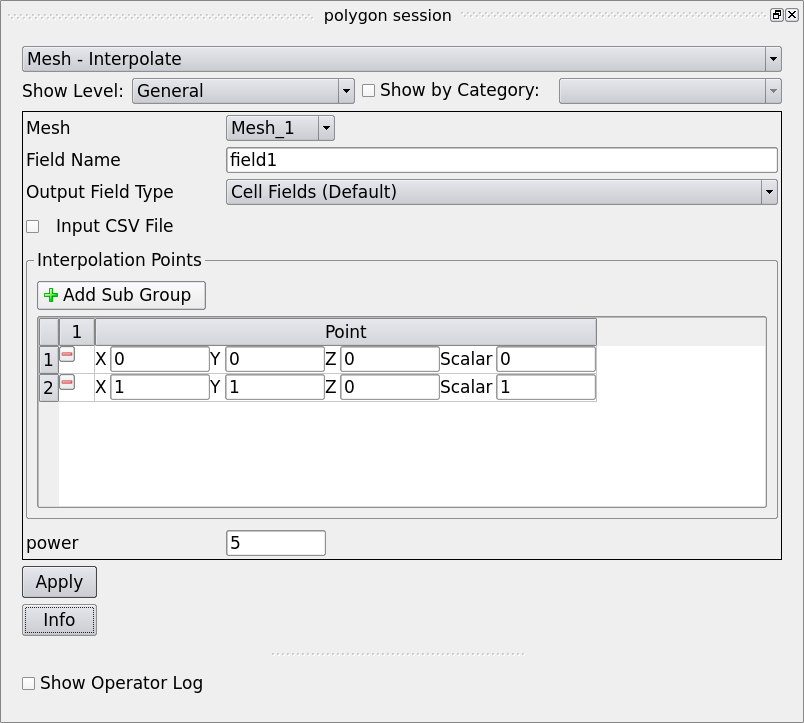
First you need to select a mesh to interpolate on, then specify a field name. After choose an output field type, you can create interpolation points where you assign the values of the field variable. In this example, two interpolation points are created, ranging from 0 to 1. The interpolation is done with Shepard’s method and the “power” entry specifies the weighting power. Hit “Apply” the field variable will be interpolated on the whole mesh.
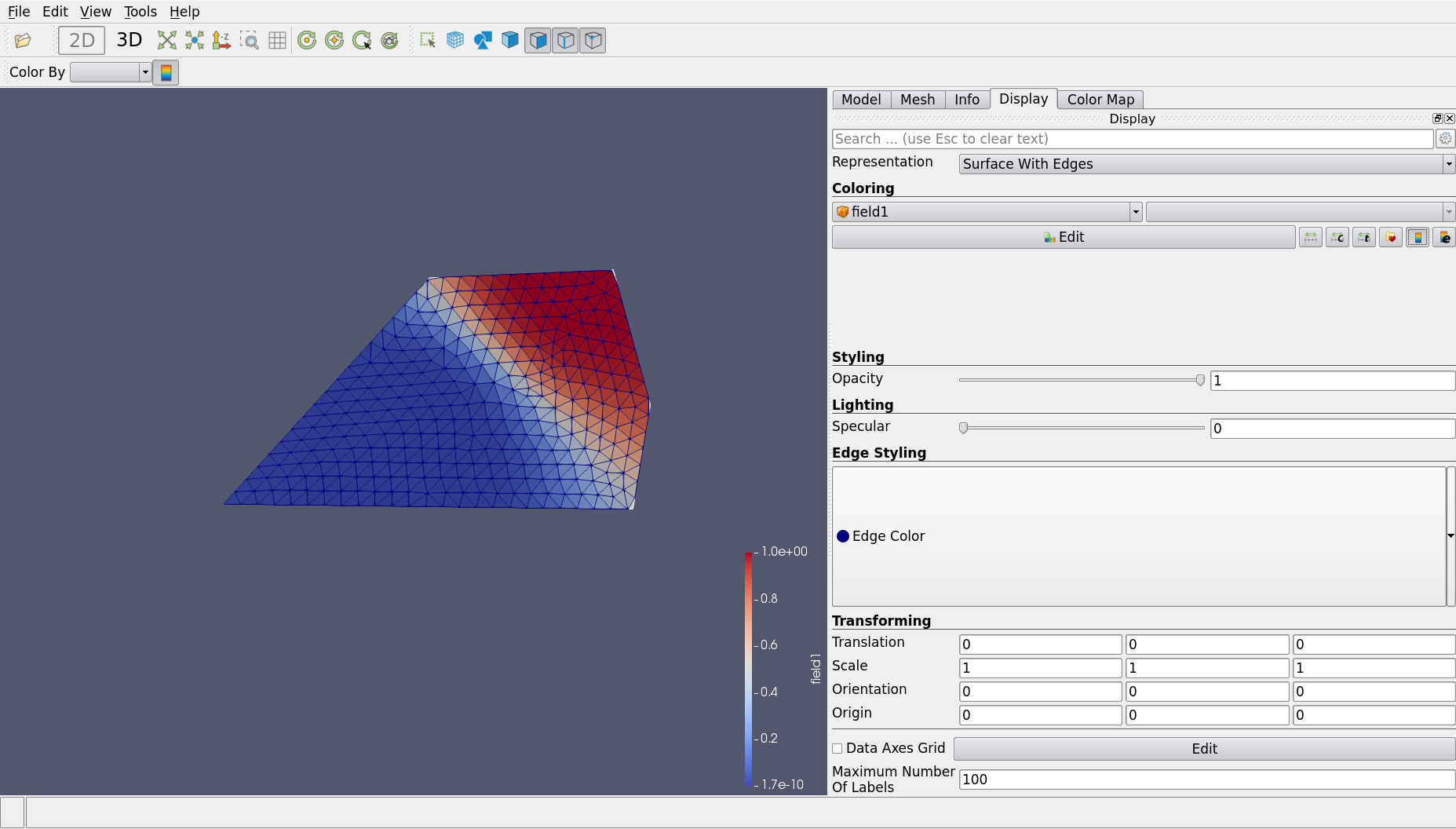
You may want to visualize the field variable. To do so, go to Display tab,
choose the field variable in Coloring. You can also click on  to bring up the legend bar.
Bathymetry can be applied to mesh through Mesh - Apply Bathymetry. We save this feature for The Discrete Session as well.